Injection Molding Weld Lines: Causes, Risks, and a Practical Diagnostic Sequence

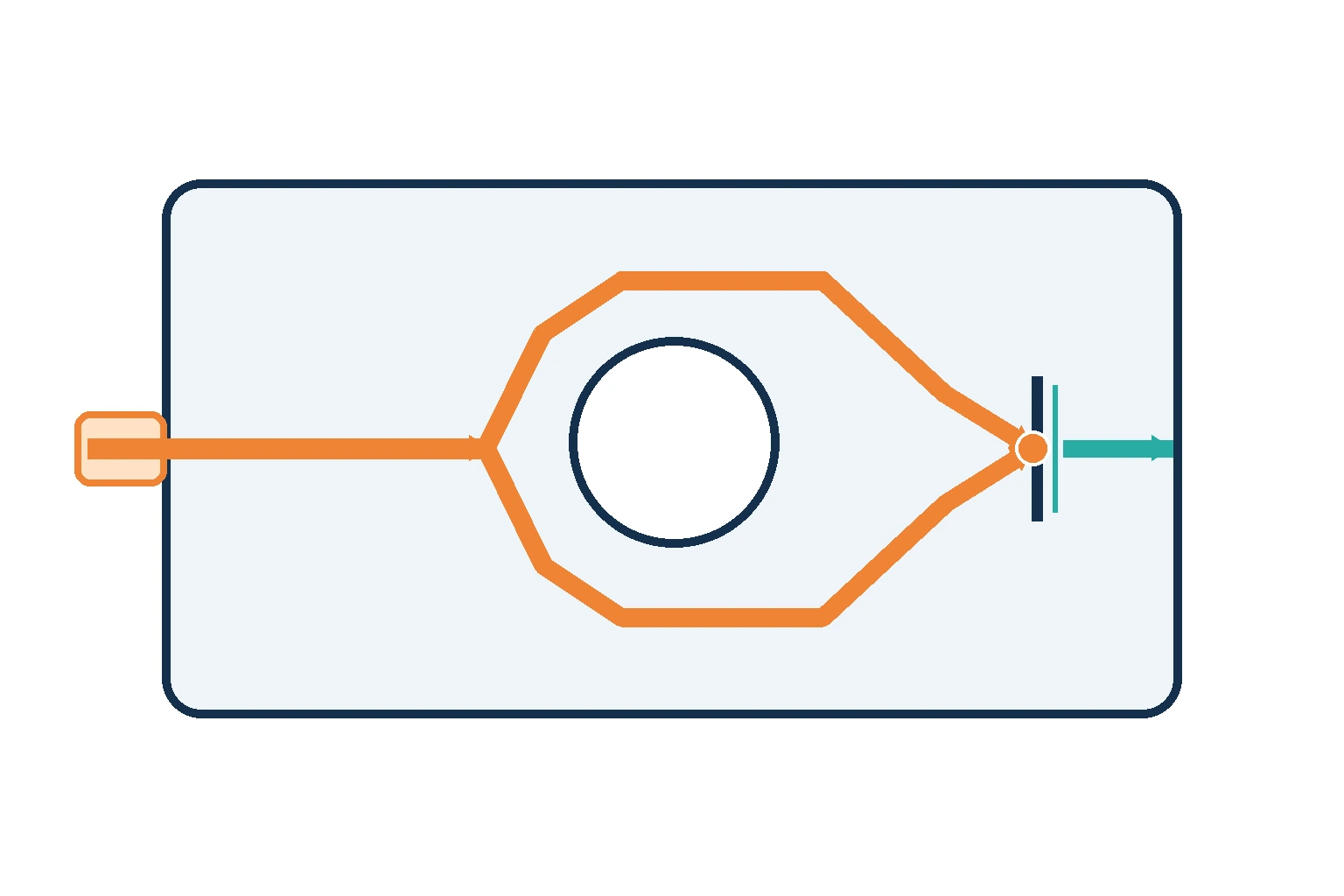
Injection molding weld lines—also called knit lines or weld marks—form where two or more melt fronts meet inside a mold cavity. The result may be a faint surface line with no practical effect, or it may be a mechanically significant interface positioned in a highly loaded region. That range of possible outcomes is why a weld line should not be accepted or rejected on appearance alone.
For engineers, the important questions are not simply, “Can the line be removed?” They are: Why did the flow split? Where did the fronts reunite? What temperature, pressure, angle, venting, and material conditions existed at that point? Does the location intersect a critical surface or load path? What evidence will demonstrate that the finished part meets its actual requirements?
This guide explains how weld lines form, distinguishes weld lines from meld lines, and provides a disciplined diagnostic order for design, tooling, process, material, and validation decisions.
How Injection Molding Weld Lines Form
Molten polymer entering a cavity advances as a flow front. When that front encounters a core pin, opening, insert, rib network, or another stream arriving from a different gate, it can divide into separate paths. Those paths may later meet downstream.
As each path travels through the cavity, heat transfers into the mold. A cooler, more viscous skin develops at the front and near the cavity surface. If the fronts meet after excessive cooling, under unfavorable pressure or venting conditions, or with limited molecular interdiffusion, the interface may remain visible and may be weaker than the surrounding material.
Common conditions that create or influence injection molding knit lines include:
- Holes, slots, windows, and core pins that divide the flow.
- Multiple gates whose flow fronts meet inside the cavity.
- Wall-thickness changes that cause hesitation or preferential flow.
- Ribs, bosses, inserts, and other features that alter the fill pattern.
- Long or restrictive flow paths that allow the fronts to cool.
- Air trapped where the fronts meet, especially near the end of fill.
- Material systems whose viscosity, reinforcement, additives, or color package affect interface formation and appearance.
These mechanisms make some weld lines geometrically unavoidable. A part with a molded-through hole, for example, normally requires the flow to split and rejoin. The realistic objective may therefore be to relocate the line, improve the interface, reduce its visibility, or validate that it is acceptable—not to promise its complete elimination.
Weld Line vs. Meld Line: Why the Distinction Matters
The terms are often used interchangeably in production discussions, but technically they describe different ways in which flow fronts meet.
Weld line
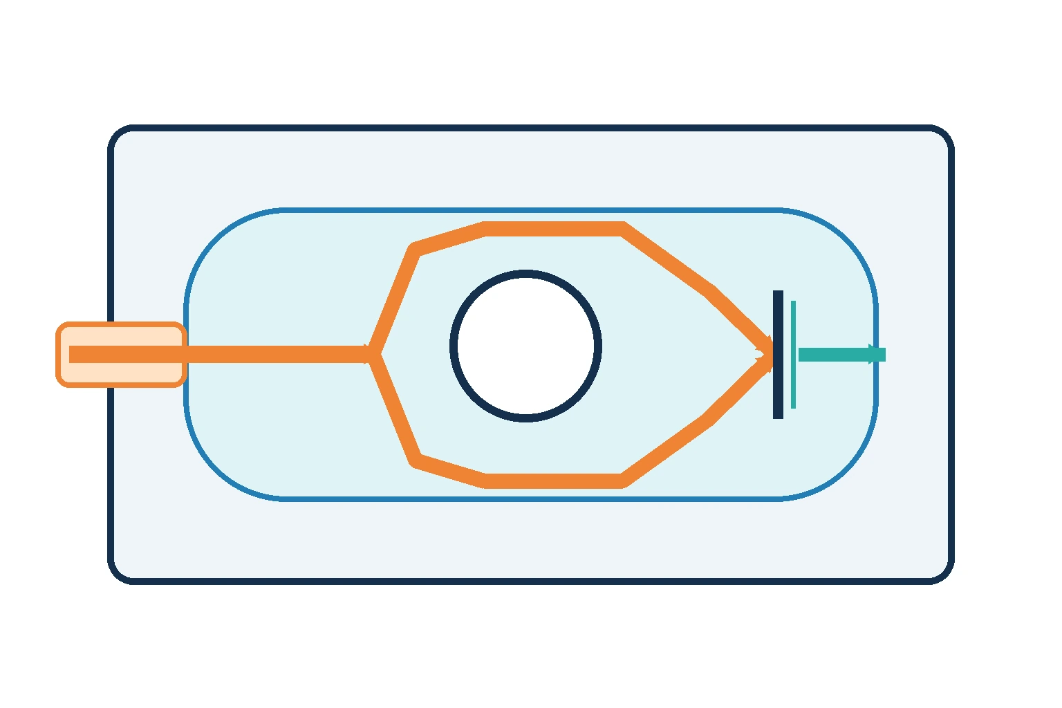
A weld line generally forms when fronts approach each other more directly. The opposing streams meet, and the combined flow may have limited opportunity to continue across and intermingle beyond the interface. This configuration can produce a more distinct surface mark and a less favorable molecular or fiber orientation pattern.
Meld line
A meld line forms when fronts meet at a more oblique angle and continue flowing together. That continued movement can promote better intermingling than a head-on meeting. Meld lines therefore tend to be less visible and potentially stronger, although neither outcome should be assumed for a specific part.
Autodesk Moldflow’s weld and meld line troubleshooting guidance explains how meeting conditions influence the interface. For project communication, specify whether the concern is any visible flow-front meeting line or a predicted head-on weld interface.
When Is a Weld Line Only a Cosmetic Issue?
A weld line may be primarily cosmetic when it appears on a noncritical surface, remains within an agreed visual standard, and does not affect fit, sealing, assembly, or required mechanical performance. Even then, acceptance needs a defined viewing and inspection method. “Looks acceptable” can vary with lighting direction, viewing distance, surface texture, gloss, color, and sample preparation.
A useful cosmetic specification can identify:
- Critical appearance surfaces.
- Permitted and prohibited weld-line zones on the drawing or 3D model.
- Color, texture, gloss, and downstream finishing requirements.
- Inspection lighting, viewing distance, orientation, and approved master samples.
- Whether a visible line is acceptable if it passes functional testing.
Colorants and fillers can change how strongly the interface is seen. Metallic or effect pigments may make flow orientation more noticeable, while surface texture may reduce visibility without improving the underlying bond. Cosmetic masking must therefore not be treated as evidence of structural improvement.
When Does a Weld Line Become a Structural Risk?
A weld line deserves structural attention when it crosses or approaches a meaningful load path. Examples include snap arms, pressure boundaries, screw bosses, clips, hinges, mounting features, sealing areas, or regions exposed to impact, fatigue, vibration, creep, chemicals, or elevated service temperature.
Risk depends on the complete application, not simply on whether a line is visible. Relevant factors include:
- The direction and duration of loading relative to the interface.
- Stress concentrations caused by notches, corners, holes, or local thickness transitions.
- Whether loading is static, cyclic, impact-related, or sustained.
- The selected resin grade, reinforcement, additives, colorant, moisture condition, and processing history.
- Flow-front temperature, meeting angle, pressure history, and air evacuation.
- Fiber orientation in reinforced polymers.
- Exposure to heat, chemicals, humidity, UV, or assembly stress.
A faint weld line can still mark a weak interface. Conversely, a visible line may satisfy the required load case. The Covestro thermoplastic weld-line white paper discusses how geometry, filling conditions, venting, gate design, fillers, and testing can affect weld-line performance. Its application-specific examples should not be converted into universal design allowables.
Visual inspection cannot validate weld-line strength
Appearance can locate a surface indication, but it cannot quantify interface strength, impact resistance, fatigue life, creep behavior, or environmental stress-cracking resistance. Polishing, texture, color changes, or thermal techniques may improve appearance without producing a proportional strength increase.
Validation should reflect the actual failure mode. Depending on the application, that may involve tensile or flexural comparison, impact testing, pressure or leak testing, assembly testing, cyclic loading, environmental conditioning, or destructive testing of representative finished parts. Test specimens and loads should represent the production material, flow orientation, gate configuration, weld-line location, and relevant process window.
A Better Diagnostic Sequence: Design, Mold, Process, Material, Validation
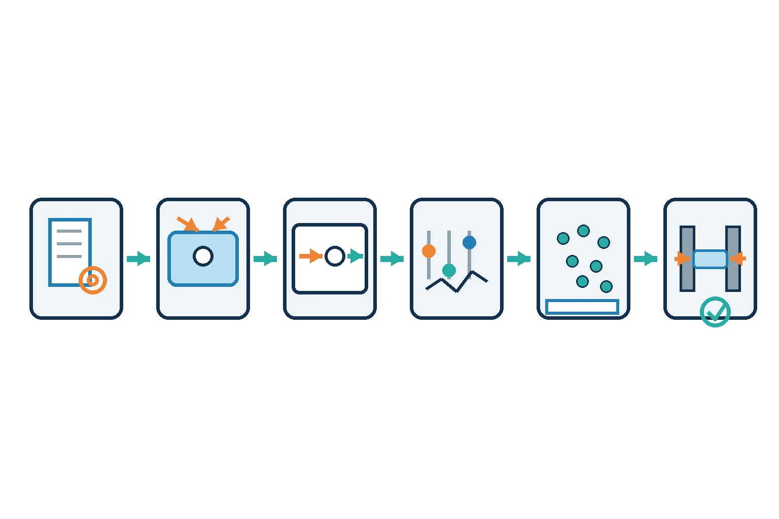
Randomly adjusting molding settings can move the defect, hide its appearance, or introduce flash, burn marks, dimensional change, residual stress, or another defect. A structured sequence is more efficient because it starts with the factors that determine whether and where flow fronts meet.
A 2024 review of weld-line minimization research groups the subject around formation causes, influencing mechanisms, numerical prediction, and improvement methods. For practical project reviews, those topics can be translated into the following order.
1. Review the part design and requirement first
Identify the feature that splits the flow and map predicted or observed lines against cosmetic surfaces and load paths. Review holes, inserts, bosses, ribs, wall transitions, and local restrictions. Ask whether a feature can move, whether the load path can be reinforced or redirected, or whether the weld line can be placed in a lower-risk zone.
Uniform walls may support more predictable filling, but geometry changes must also be checked for sink, warpage, stiffness, cooling, assembly, and packaging constraints. Related decisions can be addressed during a broader injection molding project review rather than treating weld lines as an isolated surface defect.
2. Review mold architecture and the predicted fill pattern
Gate number, type, size, sequence, and location determine how the cavity fills. Runner balance, cooling layout, and venting also affect where fronts meet and their condition at that moment. Potential actions include moving a gate, changing how flow is distributed, improving venting near the meeting zone, or evaluating a different gating strategy.
These are tooling decisions with consequences for gate vestige, pressure demand, shear, cycle behavior, dimensions, and cost. They should be evaluated together through mold design and manufacturing review, not selected from a generic remedy list.
3. Establish a controlled process study
Only after the geometry and tool are understood should the team study process variables. Melt condition, mold temperature, fill-rate profile, transfer behavior, packing, and cooling can affect interface quality. The appropriate direction and safe range depend on the specific resin grade, tool, machine, cavity, and competing defects.
Do not apply universal temperature, speed, or pressure values. Use the material supplier’s processing guidance, actual process data, short-shot studies where appropriate, and controlled trials that change defined factors while monitoring both the weld line and other quality characteristics. The Fictiv weld-line troubleshooting overview likewise separates part-design, mold-design, and processing considerations.
4. Confirm the material system
Verify the exact resin grade—not only the polymer family. Reinforcement, filler level, pigments, flame-retardant packages, regrind strategy, drying history, contamination, and degradation can all influence flow, bonding, orientation, and visibility. Review the current technical data and processing guidance from the material supplier.
A material change may improve one characteristic while altering shrinkage, warpage, chemical resistance, impact performance, appearance, or regulatory status. Material substitution should therefore follow a requirement review rather than serve as the first troubleshooting response.
5. Validate with representative parts and loads
After selecting a proposed solution, verify it across an agreed process window. Confirm weld-line location, cosmetic acceptance, dimensions, assembly behavior, and functional performance. For a critical interface, use a test that stresses the weld-line region in a manner representative of service.
Simulation can help compare fill patterns, meeting locations, temperature history, and alternative gating concepts, but it does not replace physical validation. Mesh quality, material data, boundary conditions, and model assumptions influence predictions. Final acceptance should be based on requirements and representative molded parts.
What Engineers and Buyers Should Include in an RFQ
An RFQ that identifies only resin family, annual volume, and part geometry leaves major weld-line decisions unresolved. To support a useful review, provide:
- Native CAD and a controlled drawing revision.
- The exact resin grade and approved alternatives, if any.
- Color, texture, gloss, and critical cosmetic surfaces.
- Expected weld-line restrictions or permitted zones.
- Critical dimensions, datum strategy, mating parts, and assembly method.
- Service loads, load direction, impact or fatigue exposure, and load duration.
- Operating temperature, chemicals, humidity, UV, and other environmental conditions.
- Leak, pressure, sealing, dielectric, or other functional requirements.
- Required validation methods, sampling expectations, and acceptance criteria.
- Forecast volumes and program stage so tooling decisions can be evaluated in context.
For an initial manufacturability discussion, the relevant background on production considerations is available on the injection molding service page. The RFQ itself should still define the application-specific requirements rather than rely on generic defect terminology.
Frequently Asked Questions
Are weld lines and knit lines the same thing?
In everyday molding discussions, yes. “Knit line,” “weld line,” and “weld mark” are commonly used for the interface where separated flow fronts reunite. A more technical review may distinguish a head-on weld line from an oblique meld line.
Can injection molding weld lines be eliminated completely?
Sometimes a design or gating change can avoid a particular meeting line. In parts with molded holes, openings, inserts, or multiple flow sources, some form of flow-front meeting may be unavoidable. The objective then becomes controlling location, appearance, and performance.
Does a visible weld line mean the part is weak?
Not necessarily. Visibility does not quantify mechanical performance. The application, material, geometry, flow conditions, and load path determine the risk. Representative testing is required where strength matters.
Can higher melt temperature or faster filling fix the defect?
Those changes may improve front temperature or bonding in some material-and-tool combinations, but they are not universal fixes. They may also affect degradation, flash, burns, shear, dimensions, residual stress, or cycle behavior. Changes should remain within material guidance and be evaluated through controlled trials.
Should gate relocation be considered before changing material?
Usually, the fill pattern and weld-line location should be understood before a material change is proposed. Gate relocation may move the line away from a cosmetic or structural zone, but it also affects pressure, orientation, vestige, packing, and warpage. The correct decision depends on the complete design.
Prepare the Review Around Requirements, Not Appearance Alone
Injection molding weld lines are flow-history indicators, not stand-alone pass/fail criteria. The strongest decisions connect line location to geometry, tooling, process conditions, material behavior, and the part’s real service requirements.
If you are preparing an RFQ, you may provide the CAD file, specified material, critical cosmetic surfaces, and load requirements for review. Include the acceptance or validation criteria already defined by your engineering and quality teams.