
Injection Molding Gate Design: Types, Location, and a DFM Review Checklist

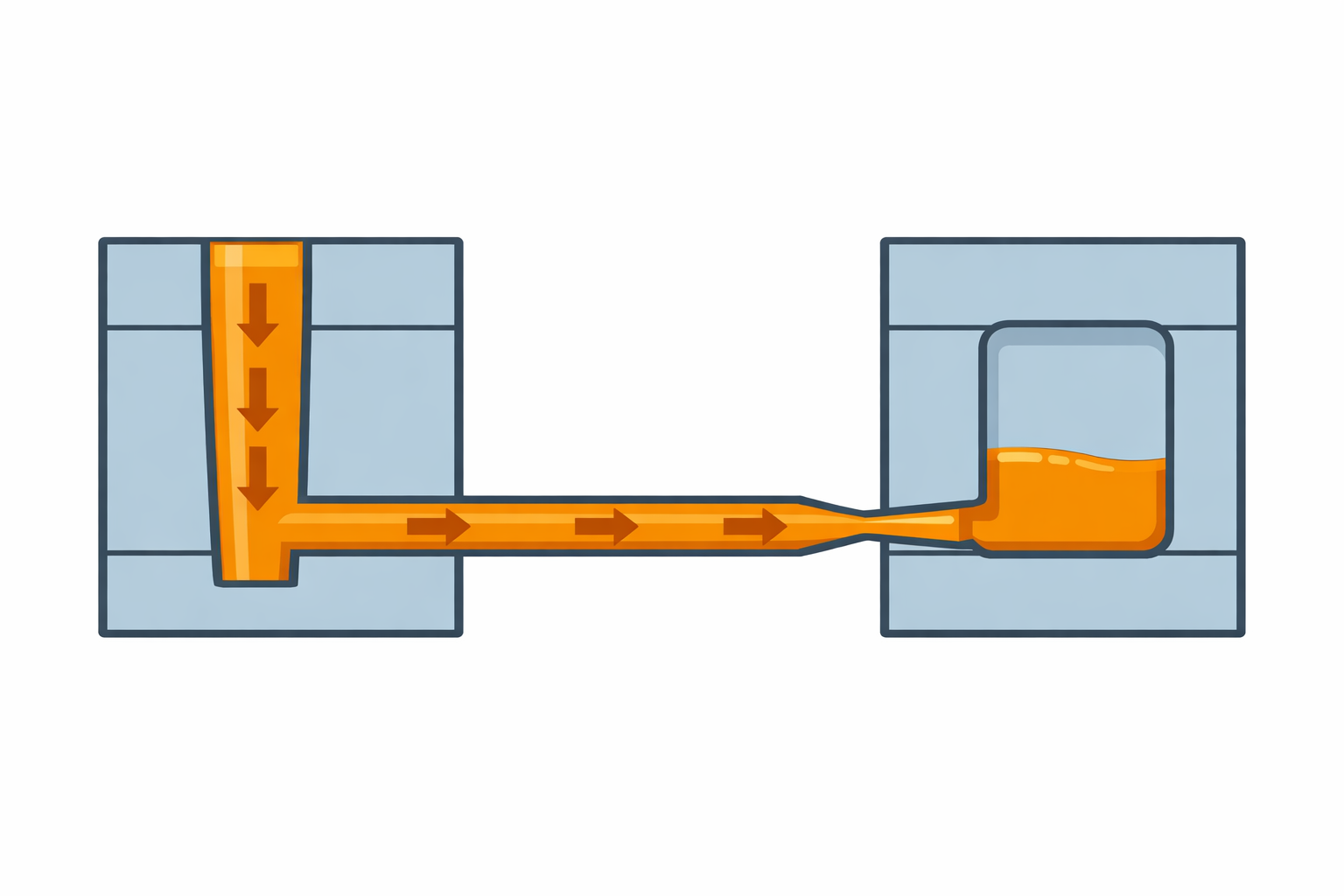
The gate is the controlled opening through which molten plastic leaves the runner system and enters the mold cavity. Its type, size, and position influence filling, flow-front meetings, packing, air escape, and the mark left after degating.
Injection molding gate design is therefore an early product and mold decision. A workable gate must fill the geometry, suit the resin, protect important surfaces and load paths, separate acceptably, and fit the mold structure. There is no universally best gate.
This guide compares common gate families, explains how to review injection molding gate location, and provides a DFM checklist for engineers and buyers before mold release.
What the Gate Must Do
A gate meters the connection between runner and cavity. It must pass melt without unacceptable pressure loss, shear, jetting, or hesitation, remain effective for required packing, and then freeze or close so the part can separate from the delivery system.
The entry region may show blush, flow marks, a trimmed edge, or a projection. Injection molding gate vestige describes material or a visible mark left after gate removal. Its acceptable form, height, sharpness, and location should be defined by the drawing or agreed cosmetic standard—not first judged at mold trial.
A gate cannot be reviewed apart from the sprue, runners, cavity, cooling, vents, and ejection. The 3D Systems injection molding basics distinguishes automatically trimmed gates from gates requiring manual separation—a DFM distinction that affects mold concept, handling, finish, and inspection.
Common Injection Molding Gate Types Compared
The names used by mold builders can vary, and some gate families overlap. The following comparison is a practical starting point rather than a substitute for a mold-specific design.
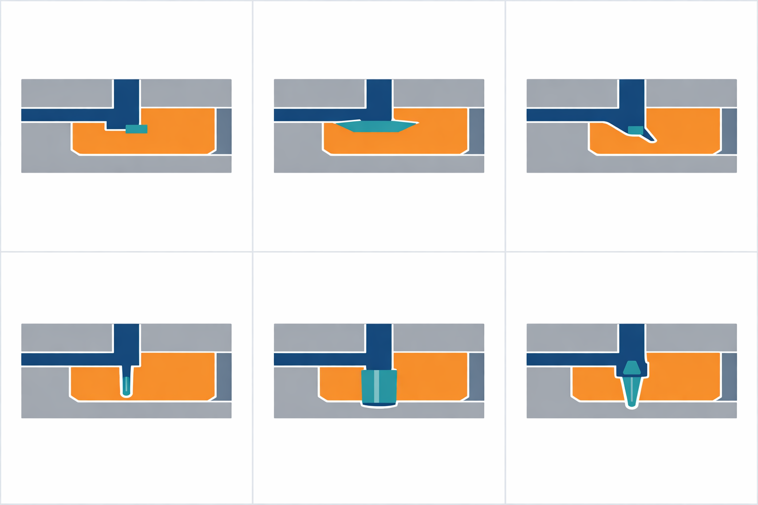
| Gate family | Basic arrangement | Typical reason to consider it | Main review concerns |
|---|---|---|---|
| Edge or side gate | Rectangular entry at the parting line | Simple construction, accessible tuning, sustained flow into an edge | Visible edge vestige, trimming access, runner attachment, asymmetric flow |
| Fan or tab gate | Wider entry or a sacrificial tab before the part | Spread flow over a wider front or isolate entry effects | Larger cleanup area, added runner/tab material, available edge space |
| Submarine or tunnel gate | Angled passage below the parting line | Automatic separation and a gate location away from the parting-line edge | Shearing behavior, resin toughness, small-section shear/freeze-off, ejection path |
| Pin or pinpoint gate | Small circular entry, often associated with three-plate or hot-runner layouts | Small point vestige and flexible cavity entry | Pressure loss, shear, gate break, tooling complexity, local appearance |
| Direct sprue gate | Sprue feeds directly into the cavity | Short delivery path for suitable single-cavity geometry | Large attachment and vestige, removal method, local stress and appearance |
| Diaphragm, disc, ring, or spoke gate | Melt enters around or toward a circular feature | More concentric filling of round or tubular parts | Gate removal, roundness requirement, trimming area, tool construction |
| Hot tip or valve gate | Heated drop delivers melt at the cavity; valve version mechanically controls opening | Eliminate a cold runner and place gates near selected cavity regions | Thermal control, material residence, maintenance, local mark, sequencing and cost |
Edge gate injection molding
An edge gate sits at the parting line and feeds the component side. Compared with less accessible styles, it is often straightforward to machine, inspect, enlarge, or repair.
Separation commonly leaves a visible edge mark and may require trimming. The DFM should show the attachment and removal method, cutter access, and any conflict with seals, snaps, mating parts, hand-contact zones, or cosmetic surfaces.
Fan and tab gates
A fan gate widens toward the cavity to spread flow. A tab gate confines some entry disturbance to a sacrificial feature. Both can suit wide, flat geometry but need space and create a wider cleanup zone.
Submarine gate injection molding
A submarine or tunnel gate approaches below the parting line and separates during ejection. It can reduce manual degating and move the witness to a hidden surface.
Automatic separation does not mean zero vestige or risk. The exact resin’s stiffness, toughness, fillers, flow, and shear response affect break-off. Geometry, gate path, ejection direction, and access constrain the design. Material-specific limits should come from the resin supplier and be checked at trial.
Pin, direct, and circumferential gates
A pin gate can leave a compact witness and support layouts difficult to feed from an edge. Its small section can increase pressure loss and local shear, so “smaller” is not automatically better.
A direct sprue gate provides a short path but creates a larger attachment needing defined removal and acceptance. Circumferential gates can suit round or tubular geometry when filling pattern or concentricity justifies added trimming and tool complexity.
Hot-tip and valve gates
A hot-tip gate uses heated delivery near the cavity; a valve gate adds a controlled pin. Both can avoid cold-runner separation but add thermal, control, maintenance, and cost concerns. Multiple valve gates need a reviewed sequence because timing moves flow-front meetings.
The Protolabs gating guide illustrates how gate style changes placement, trimming, vestige, material compatibility, and mold construction. Use such comparisons to form questions, not to copy a gate choice across unrelated parts.
How to Choose an Injection Molding Gate Location
A correct gate family can still perform poorly in the wrong position. Review location against the following objectives and conflicts.
Start with the exact resin and wall-thickness map
A common starting principle is to feed from a thicker region toward thinner regions so that pressure can continue reaching material concentrations while they cool. This is not permission to create unnecessary thick sections; uniform walls and gradual transitions remain important. If thick regions are isolated behind thin sections, the thin path may freeze before packing is complete, increasing the risk of sink marks or voids.
Gate dimensions and allowable shear cannot be selected from polymer family alone. The final review should use the exact commercial grade, filler or reinforcement, supplier processing guidance, and relevant rheology data. Toray states that gate design should be considered during product design before mold design, but its gate-design guidance is specifically for AMILAN nylon resin. Treat it as resin-supplier guidance for that material family, not a universal sizing standard for every plastic.
Shorten and balance the flow path
Long, thin, or sharply changing flow paths consume pressure and lose heat. Locate the gate so the flow can reach all required features without premature freeze-off or an unnecessarily narrow process window. On long or complex parts, more than one gate may be considered, but added gates also create added weld lines, witnesses, and balance requirements.
For multi-cavity molds, compare the runner and gate path to each cavity. Geometric symmetry alone does not prove rheological balance. The DFM should make clear how cavities are expected to fill and how cavity-to-cavity gate differences will be detected.
If filling risk is high, compare the proposed design with the causes and evidence described in the guide to injection molding short shots.
Predict weld lines and air traps together
Every gate establishes a flow pattern. Holes, cores, ribs, and multiple gates divide the melt into fronts that later rejoin. Move predicted meeting lines away from highly loaded or appearance-critical regions where practical. Review the separate guide to injection molding weld lines when a meeting line crosses a clip, boss, sealing area, or structural path.
The end-of-fill location must also allow displaced air to escape. Gate and vent planning therefore belong in the same review. A location that produces an enclosed air trap may cause burns, incomplete fill, or unstable appearance even if its flow length looks favorable.
Protect cosmetics, assembly, and measurement
Mark cosmetic zones, no-gate zones, contact areas, sealing surfaces, datums, and mating features on the controlled drawing or DFM. Do not approve a vague note such as “gate on back” when several back-side locations have different functional consequences.
The gate region may differ locally from the rest of the part because it is the melt entry, a hot region, a shear region, and later a separation point. Keep the vestige and trimming action away from measurement datums and interfaces unless the specification explicitly accounts for them. Coordinate that decision with the project’s injection molding tolerances and inspection method.
Consider orientation, shrinkage, and warpage
Flow direction can influence molecular or fiber orientation. That, in turn, can affect directional shrinkage, mechanical response, and flatness—especially for reinforced materials. Gate position should be reviewed against critical load directions and dimensional features rather than optimized only for appearance.
Balanced filling does not guarantee a flat part, because wall thickness, cooling, packing, material behavior, and ejection also matter. However, a strongly asymmetric flow and packing pattern should trigger a specific warpage review before the gate location is frozen.
The Plastics Engineering design article emphasizes that gate position affects filling, packing, aesthetics, mechanical performance, weld-line position, and air trapping. These interactions explain why moving a gate to hide its mark can simply move risk elsewhere.
DFM Review Checklist Before Mold Release
Use this checklist as a decision record. Each “yes” should point to a drawing note, DFM view, material document, simulation result, mold-layout detail, or acceptance method.
Part, material, and requirements
- Is the exact resin manufacturer and grade identified, including filler or reinforcement and approved alternatives?
- Has the team obtained the resin supplier’s current guidance for processing, gate design, shear sensitivity, and drying where applicable?
- Are nominal walls, thick transitions, ribs, bosses, and long thin flow paths visible in the review?
- Are critical-to-quality dimensions, load paths, sealing zones, assembly interfaces, and cosmetic surfaces marked?
- Does the part include sufficient draft angle for the proposed release direction and gate/ejection concept?
Gate type and mold concept
- Is the proposed gate type named consistently on the DFM and mold layout?
- Is the gate compatible with the two-plate, three-plate, cold-runner, or hot-runner concept?
- Is manual versus automatic degating explicit?
- Can the gate and runner release without part damage, runner hang-up, or interference with ejectors, slides, lifters, or inserts?
- Is the gate accessible for machining, inspection, expected tuning, maintenance, and repair?
Location, filling, and packing
- Does the proposed location support a short, balanced flow path into the actual wall-thickness map?
- Can pressure reach thicker regions before connecting sections freeze?
- Are hesitation, jetting, and abrupt flow-direction changes addressed?
- For multiple gates or cavities, is balance evaluated beyond simple geometric distance?
- Are predicted weld lines away from critical cosmetic, sealing, and loaded regions where practical?
- Are last-to-fill areas identified, and is there a venting path at those locations?
- If simulation is used, are material data, assumptions, gate geometry, runner layout, and version controlled? Simulation should guide decisions, not be presented as proof of production performance.
Vestige, finishing, and acceptance
- Is the allowed gate-mark zone defined on the drawing or approved visual standard?
- Are the permitted vestige form, projection, sharpness, whitening, blush, and surrounding surface condition specified in testable language?
- Is the trimming or automatic break method defined, including who performs any secondary operation?
- Can the finished location be inspected without subjective interpretation?
- Has the team checked whether trimming can affect a seal, datum, fit, hand-contact surface, coating, texture, or downstream assembly?
Trial and change plan
- Does the mold-trial plan record fill pattern, part weight, cavity balance, gate appearance, weld lines, air traps, and relevant dimensions?
- Are gate changes planned in a direction that can be made deliberately, with review before irreversible steel changes?
- Is there a controlled method to approve relocation, enlargement, repair, or hot-runner timing changes?
- Will trial results be checked for new sink, short shot, flash, weld-line, warpage, dimensional, cosmetic, and ejection risks?
- Are drawing revision, DFM approval, mold data, samples, and deviation decisions retained as one controlled record?
What Buyers Should Request in the Mold Review
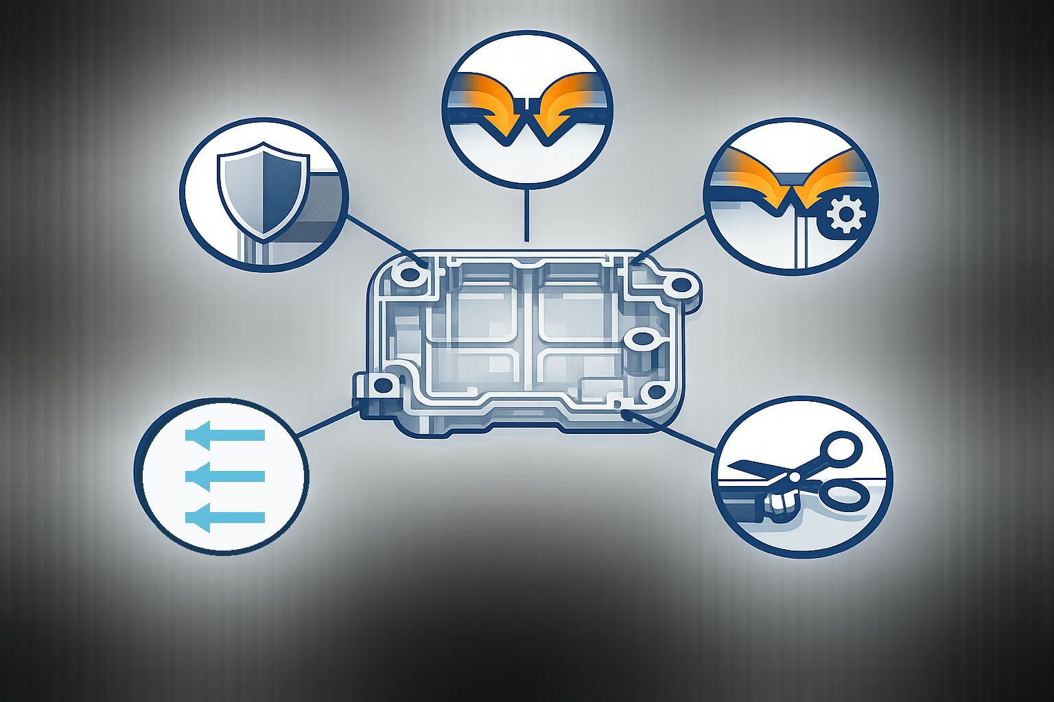
Procurement need not redesign the gate, but should make the decision auditable. Ask for a gate/runner layout showing type, count, location, and degating method. Provide controlled CAD and drawing revisions, exact resin grade, cosmetic zones, critical dimensions, inspection method, assembly constraints, and allowed vestige areas.
For higher-risk geometry, ask how the proposal addresses balance, pressure path, weld lines, venting, and directional shrinkage. If flow analysis is supplied, request its assumptions and design revision—not only a screenshot. Separate predictions from trial checks.
“Automatic gate” does not define an acceptable surface, and “trim flush” does not define inspection. Resolve both in an acceptance note before the mold is built.
Frequently Asked Questions
What is the best gate type for injection molding?
There is no single best type. The choice depends on part geometry, exact resin grade, wall thickness, mold layout, filling and packing needs, cosmetic zones, acceptable vestige, degating method, production economics, and maintenance. Compare at least the simplest workable concept with any more complex alternative.
Where should an injection molding gate be located?
A useful starting point is a thick region that supports flow toward thinner areas while keeping the flow path short and balanced. The final location must also control weld lines, air traps, vestige, orientation, critical dimensions, appearance, and mold mechanics. These requirements can conflict, so location should be approved through DFM rather than a single rule of thumb.
Does a submarine gate leave no mark?
No. It separates automatically and can place the witness on a less visible surface, but it still leaves a gate area that may show a projection, whitening, tear, or other local effect. Specify and inspect the acceptable result.
Can a gate be moved after the mold is built?
Sometimes, but relocation may require closing the original entry, changing runners or inserts, machining a new route, and revalidating filling, cooling, ejection, dimensions, and appearance. The feasibility and risk depend on the mold construction. It is usually better to compare locations before steel release.
Should gate size come from a generic chart?
A chart can provide a discussion point, not final approval. Gate size must account for the exact resin grade, wall thickness, flow length, cavity volume, gate type, runner system, packing requirement, shear and thermal limits, vestige, and mold process. Material-specific guidance should come from the resin supplier.
Is mold-flow simulation required for every gate decision?
Not every part has the same risk or justifies the same analysis. Simulation is most useful when geometry, multiple gates, thin walls, reinforced resin, critical weld lines, flatness, or cavity balance makes intuition uncertain. Its output still depends on accurate material data and inputs and must be checked against mold-trial evidence.
Conclusion
Injection molding gate design coordinates type, size, location, material, mold architecture, and acceptance. An edge gate may favor simplicity; a submarine gate may favor automatic separation and a hidden witness; other families solve different flow and layout needs. Every choice still requires review of the exact resin and part.
Before approving the mold, confirm where the melt enters, where it travels, where fronts meet, where air escapes, how thicker regions remain connected for packing, how the gate separates, and what finished vestige is acceptable. A documented DFM decision gives engineering, quality, sourcing, and the mold supplier the same basis for trial and change control.
If you are preparing an RFQ or reviewing a mold concept, see FULU Plastics’ services overview and share the controlled part data, resin grade, surface zones, critical requirements, and gate questions for project-specific review.