
Injection Molding Short Shots: Causes and a Practical Troubleshooting Sequence

Injection Molding Short Shots: Causes and a Practical Troubleshooting Sequence
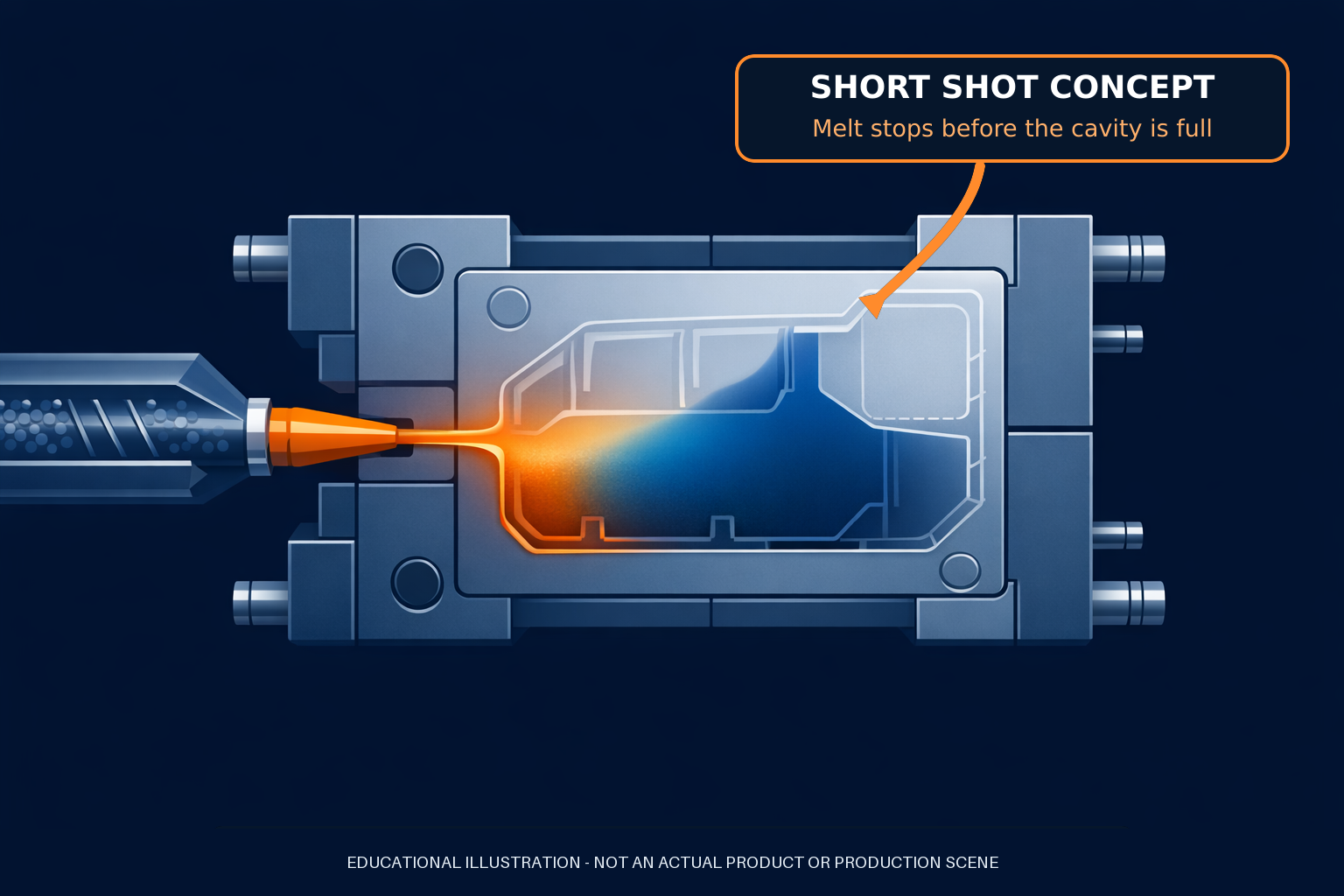
A short shot occurs when molten plastic does not completely fill an injection mold cavity. The result may be a missing corner, an incomplete rib, a thin wall that ends early, or an entire cavity that fails to fill. The defect is usually easy to see, but its root cause is not always obvious.
The common reaction is to add pressure, speed, or material. That may help in some cases, but it can also hide the real limitation or create a different defect. A better approach is to identify where the fill stops, determine what is limiting flow, and test one controlled change against a stable baseline.
This guide explains the main causes of injection molding short shots, how to organize the evidence, and what engineers and buyers should resolve before authorizing process or tooling changes.
What Is a Short Shot Defect?
A short shot is an incompletely formed molded part caused by the cavity not receiving enough flowing material before filling stops. Autodesk describes the condition as incomplete filling in which the flow freezes before the flow paths are complete. The missing region often appears at a last-to-fill location, at the end of a long or thin flow path, in a difficult rib, or in one cavity of a multi-cavity mold.
A short shot differs from several defects that can look related:
- Sink marks are surface depressions associated with localized shrinkage, often near thick sections, ribs, or bosses. The exterior geometry is still present.
- Voids are internal gaps or pockets that may not be visible from the surface.
- Weld lines form where separate flow fronts meet; the part may be fully formed even though the meeting line creates a cosmetic or structural concern.
- Flash is excess material escaping beyond the intended cavity boundary—the opposite visual condition from an incomplete fill.
For related defect mechanisms, see the guides to injection molding sink marks, weld lines, and warpage.
Why Short Shots Happen
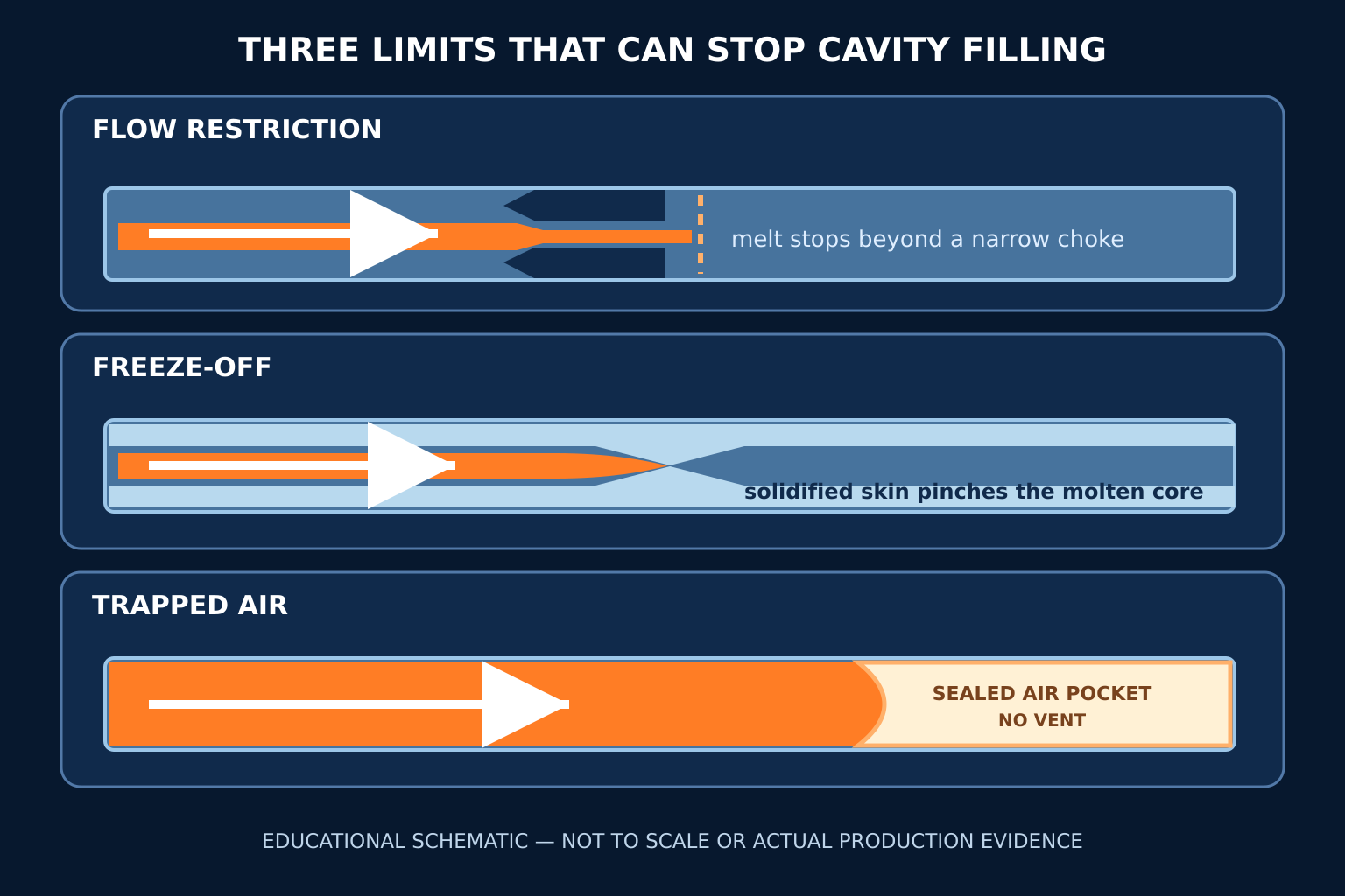
A cavity fills only while the melt can keep moving through the delivery system and part geometry. In practical terms, short shots usually point to one or more of three physical limits: excessive pressure loss, premature freeze-off, or gas that cannot escape.
1. Excessive pressure loss or flow restriction
The injection unit must move material through the nozzle, sprue, runners, gates, and cavity. Each section consumes part of the available pressure. Long flow paths, restrictive runners or gates, abrupt transitions, thin walls, and complex geometry can increase resistance until the flow front stops.
A blocked gate, cold slug, contamination, or damaged flow channel can create a similar symptom. In a multi-cavity tool, a runner imbalance may allow some cavities to fill while another remains short.
The important distinction is between available pressure and pressure actually reaching the flow front. Raising a machine limit does not correct a physical restriction; it may only drive the system harder against the same bottleneck.
2. Premature freeze-off
The melt begins losing heat as soon as it contacts the cooler mold surface. A solidified skin develops at the wall while the molten core continues forward. If the effective flow channel closes before the cavity is complete, the flow freezes off.
This can be influenced by melt temperature, mold temperature, injection speed, material viscosity, wall thickness, flow length, and hesitation. A thin feature connected to a thicker region may pause while the thicker region continues to fill; the paused section can cool enough that flow cannot restart.
Any temperature or speed change must remain within the resin supplier’s processing guidance and the validated process window. “Hotter” and “faster” are not universal solutions because excessive heat or shear can damage material or create other defects.
3. Trapped air and inadequate venting
Air occupies the empty cavity before injection. It must leave as the melt advances. If a last-to-fill region lacks an effective escape path, compressed gas can oppose the flow front and stop filling.
The location of the short is valuable evidence. A repeatable incomplete area at the end of fill—especially when accompanied by signs of gas compression or deposits near vents—should prompt an inspection of vent location, condition, and flow pattern. Cleaning a blocked vent and redesigning an inadequate vent are different actions, so the mold condition should be checked before deciding on a permanent modification.
4. Process setup and shot delivery
An incomplete fill can also result when the process does not deliver a stable volume at the required rate. Relevant checks may include the documented setup, transfer position, cushion consistency, fill time, actual pressure behavior, and shot-to-shot part weight.
Do not assume pack pressure can rescue a significantly incomplete first-stage fill. The fill and pack stages perform different functions, and the evidence should show where the process begins to depart from the approved baseline.
5. Material condition or material change
A change in resin grade, lot, moisture condition, regrind level, colorant, or handling can change flow behavior. The correct response depends on the specific material. Drying requirements, allowable regrind, melt-temperature limits, and residence-time guidance should come from the material supplier and the approved process—not from a generic troubleshooting table.
When a short shot begins after a material change, record the change rather than compensating immediately with unrelated machine adjustments.
6. Machine or delivery-system condition
A worn or malfunctioning non-return valve can allow inconsistent material delivery. A blocked feed throat, nozzle restriction, heater problem, unstable recovery, or inadequate injection-unit capability can also appear as incomplete fill.
Machine size should not be judged by clamp force alone. Shot capacity, injection pressure, injection rate, screw condition, and the actual process requirement all matter. Maintenance and machine data are therefore part of root-cause diagnosis, not an afterthought.
Read the Short-Shot Pattern Before Changing Anything
The defect pattern can narrow the investigation:
- The same feature is short on every cycle: look for a local flow-path, geometry, gate, or venting limitation.
- The short varies from shot to shot: check delivery consistency, material condition, temperature control, and mechanical repeatability.
- One cavity is short in a multi-cavity mold: compare runner balance, gate condition, venting, cavity temperature, and cavity-specific restrictions.
- The defect appeared suddenly after stable production: identify what changed—material lot, setup, maintenance, mold condition, machine, operator, or environment.
- The short occurs at a thin section after a thicker branch fills: investigate hesitation and local freeze-off.
- The short moves when a controlled variable changes: document the direction and magnitude of the response; this is stronger evidence than a one-time “good” part.
Photograph the defect from a consistent angle, mark the cavity and feature, retain representative samples, and record the production context. A buyer reviewing a supplier’s corrective action should expect evidence that connects the defect to a tested mechanism.
A Practical Diagnostic Sequence
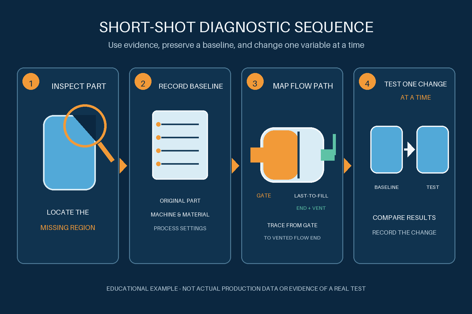
Random adjustments make it difficult to tell which action changed the result. Use a sequence that preserves the baseline and separates process, material, mold, and machine factors.
Step 1: Define the defect precisely
Record the part number, revision, material, color, cavity number, machine, mold, time, and affected feature. Determine whether the geometry is truly missing or whether the apparent problem is sink, flash, damage during ejection, or another defect.
Compare the part with the drawing, an approved sample, or a known-good part. Note whether the short is repeatable and whether its boundary is stable.
Step 2: Confirm the baseline
Compare the current setup with the approved process record. Review actual values rather than only setpoints where data are available. Check whether the process is pressure-limited, whether fill time has shifted, whether cushion and part weight are stable, and whether temperatures have reached a stable condition.
If no approved baseline exists, create a documented starting condition before testing. Without it, later conclusions will be difficult to reproduce.
Step 3: Check recent changes
Ask what changed immediately before the defect appeared. A new resin lot, maintenance activity, mold cleaning, machine transfer, changed parameter, blocked gate, or altered drying condition can provide a faster path to the cause than broad trial and error.
Step 4: Inspect material delivery and machine condition
Verify material availability and handling, then inspect the feed path, nozzle, heaters, recovery consistency, and non-return behavior as appropriate. Use maintenance evidence and machine data. Do not compensate for an unstable delivery system by rewriting the molding window.
Step 5: Inspect the mold and flow path
Check the sprue, runners, gates, vents, last-to-fill locations, and cavity-specific conditions. Look for contamination, damage, blockage, vent deposits, or an imbalance that explains the pattern. If a simulation is available, compare its predicted fill sequence and air traps with the actual defect location—but treat simulation as a model, not proof.
Step 6: Run one controlled test at a time
Choose a test that can distinguish between competing causes. Keep other conditions stable, record the change, and compare the response with the baseline. A good test answers a question such as:
- Does the fill length respond consistently to a permitted change in fill-stage conditions?
- Does restoring a blocked vent change the same last-to-fill region?
- Does the cavity imbalance follow a gate or runner restriction?
- Does delivery variation correlate with cushion or part-weight variation?
All process changes should remain within approved safety, material, machine, mold, and quality limits. A generic article cannot define those limits for a specific application.
Step 7: Verify the correction over time
One complete part does not prove a robust correction. Confirm repeatability across an appropriate run, inspect the affected feature, review dimensions or functional requirements where relevant, and ensure that the action did not introduce flash, burning, degradation, warpage, sink, or another problem.
Design and Tooling Questions to Address Before Steel Is Final
Some short-shot risks are easier to reduce during design review than after tooling is complete. Before mold release, review:
- wall thickness transitions and thin end-of-fill features;
- flow length and likely hesitation regions;
- gate count, type, location, and accessibility;
- runner balance for multi-cavity or multi-gate designs;
- predicted last-to-fill areas and venting strategy;
- material flow behavior using the exact intended grade;
- interaction between cosmetic, dimensional, structural, and gating requirements;
- how changes would affect the parting line, ejection, weld lines, and tool complexity.
Draft also affects release after the cavity fills. The separate guide to draft angle in injection molding explains what engineers should resolve for clean part ejection.
What to Include in an RFQ or Corrective-Action Request
A clear evidence package helps a molding supplier evaluate the problem without guessing. Include what is available:
- 3D CAD and a controlled 2D drawing with revision level.
- Resin manufacturer, exact grade, color, and material specification.
- Part weight, critical features, cosmetic zones, and functional requirements.
- Photos of the short shot and an approved part from the same viewing angle.
- Cavity identification and whether the defect is constant or intermittent.
- Known-good and current process records, with actual data where available.
- A timeline of material, setup, maintenance, mold, and machine changes.
- Tool layout, gate/runner information, venting details, and simulation results when available.
- The tests already completed and the response to each controlled change.
- The proposed corrective action and how its effectiveness will be verified.
For an early design review or an RFQ package, you can review FULU Plastics’ injection molding and mold-related services. Keep the request focused on the part, material, evidence, and acceptance requirements rather than asking for an unsupported universal setting.
Frequently Asked Questions
Can increasing injection pressure always fix a short shot?
No. More available pressure may extend fill when the process is pressure-limited, but it does not automatically correct a blocked gate, unstable shot delivery, frozen flow path, trapped air, or unsuitable geometry. It can also create other defects or exceed approved limits. Diagnose the limiting mechanism first.
How can I tell whether venting is involved?
A repeatable short at a last-to-fill location, especially with evidence of gas compression or contaminated vents, can point toward venting. Inspect vent location and condition, compare the observed fill pattern, and run a controlled test. The part alone may not prove the cause.
Why does only one cavity short in a multi-cavity mold?
Possible causes include runner imbalance, gate variation or blockage, cavity-specific venting, local temperature differences, or dimensional differences in the flow path. Compare cavities under the same cycle rather than treating the result as a global machine problem.
Is a short shot only a cosmetic defect?
Usually not. A missing edge, wall, rib, clip, boss, or sealing feature can affect fit, strength, assembly, sealing, and function. Acceptance should be based on the drawing and application requirements, not appearance alone.
Should a mold be modified immediately when short shots appear?
Not until process, material, machine, mold condition, and defect evidence have been reviewed. A tooling change may be appropriate when the root cause is a persistent flow-path, gate, runner, venting, or geometry limitation, but changing steel before isolating the cause can add cost without resolving the defect.
Conclusion
Injection molding short shots are simple to recognize but can come from several different limits. The cavity may be losing too much pressure, the flow front may freeze before completion, trapped air may resist filling, or the material-delivery system may be unstable. The visible defect is the starting point, not the diagnosis.
The most reliable troubleshooting sequence is to define the missing region, confirm the baseline, identify recent changes, inspect material and machine delivery, inspect the mold and flow path, and test one controlled change at a time. That approach gives engineers, suppliers, and buyers evidence they can use to choose a process correction, maintenance action, or tooling decision with less guesswork.