Injection Molding Warpage: Causes, Diagnosis, and Prevention

Injection Molding Warpage: Causes, Diagnosis, and Prevention
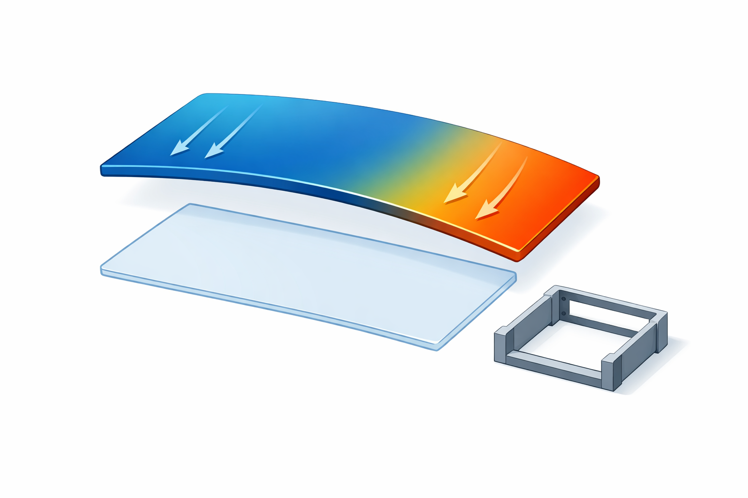
A molded part can leave the tool looking acceptable yet fail to sit flat, align with mating components, or hold its intended profile. That distortion is warpage. It is not one isolated defect with one universal setting change. Injection molding warpage is the visible result of unequal shrinkage and the internal stresses created as different regions, layers, or directions of a part cool and solidify.
Effective troubleshooting therefore starts with a question: what is shrinking differently, and why? The answer may involve part geometry, resin behavior, gate location, cooling layout, processing history, ejection, or even the way the part is conditioned and measured. This guide organizes those possibilities into a practical diagnosis and prevention workflow.
What Is Warpage in Injection Molding?
All thermoplastics contract as they cool. Uniform contraction mainly changes overall size. Warpage occurs when contraction is not uniform, so one region or direction pulls against another. The part relieves some of that imbalance by bending, twisting, bowing, or changing angular relationships.
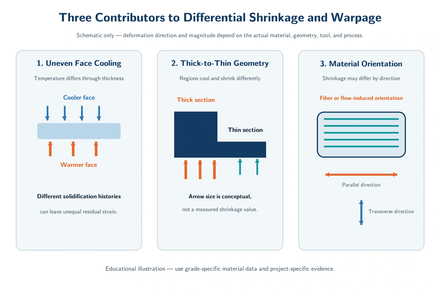
Autodesk separates major warpage contributions into differential cooling, differential shrinkage from region to region, and orientation effects caused by molecular or fiber alignment.[1] These mechanisms often interact. A gate may establish a directional flow pattern, a thick transition may cool later than a neighboring wall, and asymmetric mold temperatures may add a through-thickness stress gradient.
Warpage is also different from a sink mark. Sink is a localized surface depression, commonly associated with shrinkage near a thicker section. Warpage changes the broader shape or alignment of the part. Both can trace back to shrinkage, but they require different acceptance criteria and may point to different dominant causes.
Why Injection-Molded Parts Warp
Design: geometry creates unequal thermal and structural behavior
Abrupt wall changes, heavy intersections, uneven ribs, isolated masses, and asymmetric features do not cool or shrink alike. Even if the nominal wall is consistent, an unbalanced cross-section can resist contraction on one side more than the other. Long unsupported spans and low-stiffness shapes may then amplify a small shrinkage difference into visible bow.
Assembly requirements matter too. A free part may settle into one shape, while a constrained part may appear flat but carry stress that emerges after unclamping, heating, moisture exposure, or time. Designers should therefore evaluate both the free-state geometry and the installed boundary conditions.
Material: shrinkage may vary by grade, direction, and history
Resin family alone is not enough to predict the outcome. Crystallization behavior, fillers, fiber reinforcement, pigment packages, moisture history, regrind strategy, and grade-specific rheology can change shrinkage and orientation. Reinforced materials may shrink differently parallel and transverse to flow, making gate-driven orientation central to warpage diagnosis.
Material substitution can therefore solve one concern while creating another. Compare the exact grade, supplier data, lot controls, drying requirements, and approved material specification before attributing a shape change to processing.
Tooling: gate, cooling, venting, and ejection influence stress
Gate type and location establish the filling pattern and affect how holding pressure reaches different regions before the gate freezes. A poorly balanced filling pattern can produce uneven orientation or packing. Cooling circuits that remove heat unevenly may create temperature differences between regions or between core and cavity faces. Autodesk’s warpage guidance explicitly treats differential cooling as a separate source of deflection.[2]
Ejection can add distortion when the part is still compliant, release resistance is uneven, or ejector forces are unbalanced. Tool condition also belongs in the investigation: restricted cooling passages, damaged vents, surface changes, or inconsistent mold movement can make a previously stable process behave differently.
Process: settings determine how the designed system is realized
Fill behavior, transfer timing, holding-pressure profile, gate-seal behavior, melt and mold thermal conditions, cooling time, cycle consistency, and ejection timing all influence the stress state at release. The relevant question is not whether a setting is “high” or “low” in isolation. It is whether the complete process fills, packs, cools, and ejects the selected material consistently within its validated processing window.
A process change can also trade one defect for another. More packing may change dimensions or flash risk; a thermal change may alter surface appearance, crystallization, or cycle stability. BASF’s troubleshooting guide emphasizes that molded-part design, mold design, material properties, and processing parameters interact rather than acting as independent variables.[3]
Measurement: apparent warpage can be a definition problem
Before adjusting a tool or process, make sure everyone is measuring the same condition. A flexible part can conform to a fixture, rock on an unstable surface, or change shape with temperature, moisture, elapsed time, and assembly load. Measurement force and datum setup can either hide or exaggerate deformation.
Define the drawing requirement: which surface, line profile, flatness control, angular relationship, or functional gap is failing? Record the datum reference frame, fixture, measurement method, part age, conditioning, and free or constrained state. ISO 294-4 distinguishes molding shrinkage from post-molding shrinkage and addresses directions parallel and normal to flow, illustrating why timing and direction should be explicit when shrinkage evidence is compared.[4]
How to Prevent Warpage Before Tooling
The least disruptive injection molding warpage solutions begin before steel is cut. Prevention is not a promise of zero deformation; it is a structured effort to reduce imbalance and make remaining risk measurable.
- Clarify functional requirements. Identify critical interfaces, datum features, sealing surfaces, cosmetic zones, and whether acceptance applies in a free or assembled state.
- Promote balanced geometry. Keep wall transitions gradual, avoid isolated mass where possible, and use ribs or curvature to add stiffness without creating new heavy sections.
- Review gate strategy with flow direction in mind. Consider how gate position affects fill balance, weld locations, orientation, packing access, and the likely direction of shrinkage.
- Plan cooling around the actual geometry. Look for regions where cores, slides, inserts, deep features, or unequal steel conditions could make heat removal asymmetric.
- Select the exact material grade early. Use grade-specific data and account for reinforcement direction, moisture handling, color/additive changes, and approved substitution rules.
- Use simulation as a risk tool, not a guarantee. Fill, pack, cool, and warp analysis can compare alternatives and isolate likely contributors, but the model depends on accurate material, geometry, tooling, and process inputs.
- Leave a correction strategy. Decide which dimensions or surfaces could be adjusted safely after trials and which interfaces cannot tolerate late geometry changes.
- Build an inspection plan. Align the CAD revision, drawing, CTQs, datums, fixture concept, sample timing, and reporting format before first samples.
For related guidance on defining dimensions and measurement conditions, see Injection Molding Tolerances: A Practical Guide for Drawings and RFQs.
A Practical Troubleshooting Sequence
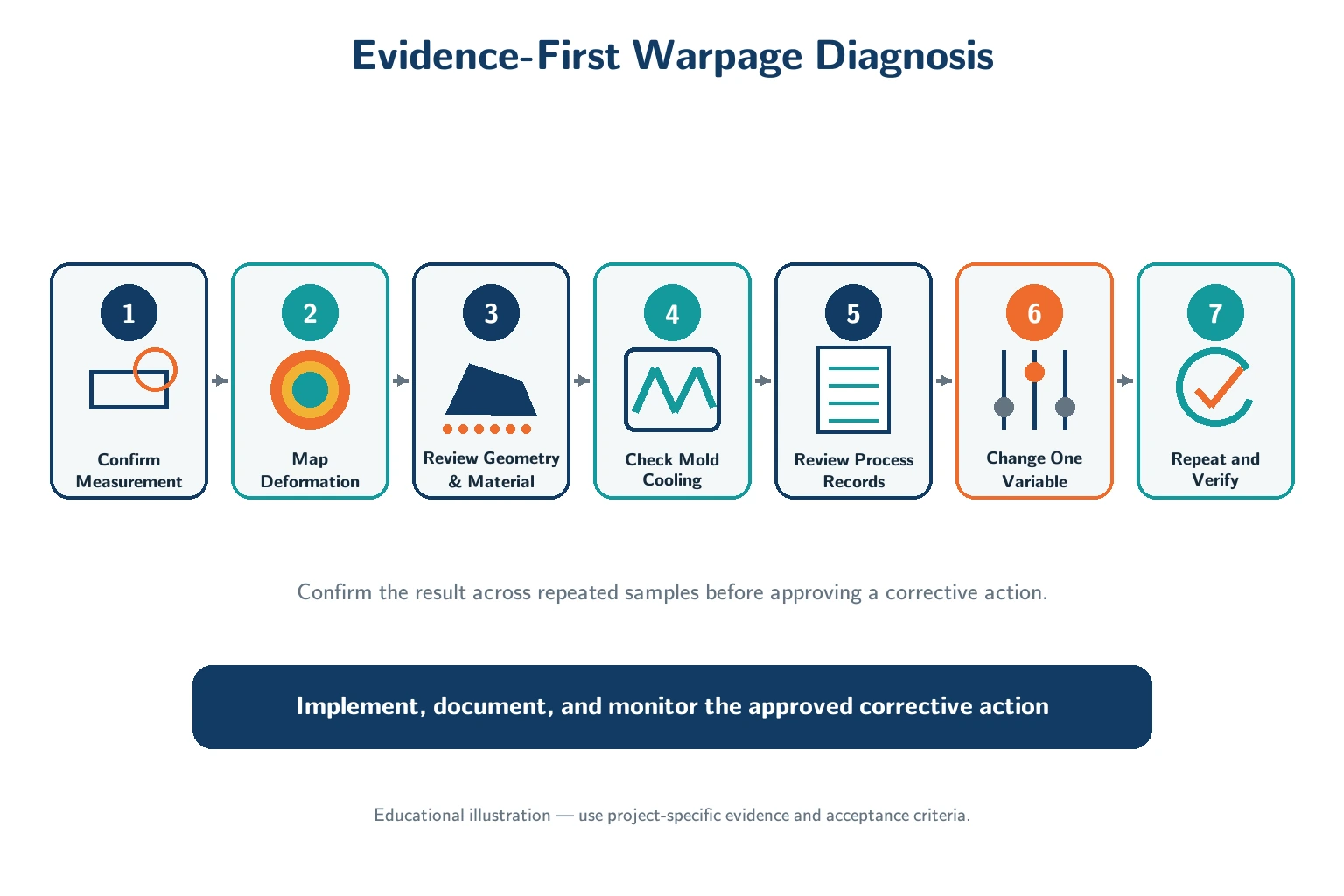
1. Verify and map the symptom
Confirm the correct part revision and acceptance requirement. Measure multiple parts from identified cavities and cycles under the same conditioning and fixturing method. Record the direction, location, and shape of deformation rather than reducing the issue to a single pass/fail label. Note whether the distortion appears immediately, after storage, or only during assembly.
2. Establish a stable baseline
Capture the actual material identity, lot and preparation history, machine and mold state, cycle record, cavity, part weight where relevant, and environmental/measurement conditions. Separate a gradual drift from a sudden change. A sudden change directs attention toward material, equipment, tool condition, or setup changes; a repeatable geometry-linked pattern may point more strongly toward design, flow, or cooling balance.
3. Classify likely causes
Review the evidence through the five categories above: design, material, tooling, process, and measurement. Look for signatures. Opposite-face bow may suggest a through-thickness thermal imbalance. Distortion aligned with flow may suggest orientation. A local pull near a heavy feature may indicate regional shrinkage. Treat these as hypotheses, not conclusions.
4. Check fundamentals before optimizing
Verify that the process follows the selected grade’s approved handling and processing guidance; that filling and transfer are repeatable; that holding remains effective as intended; that cooling and mold temperatures are stable; and that ejection is not mechanically deforming the part. Inspect the tool for obvious flow, venting, cooling, release, or maintenance issues.
5. Change one controlled factor at a time
Use a documented trial plan. Choose a variable tied to the leading hypothesis, keep other influential conditions controlled, and evaluate both warpage and side effects. Do not chase flatness by stacking several undocumented adjustments. If a process change cannot create a stable result without violating another requirement, revisit geometry, gate, cooling, material, or the specification itself.
6. Confirm repeatability and downstream function
Repeat the candidate condition across enough cycles and relevant cavities to distinguish a real shift from normal variation. Recheck dimensions, appearance, assembly, and any other critical requirements. Then lock the approved setup, revision, measurement method, and change record.
Warpage Information to Include in an RFQ
A useful RFQ gives the molding team enough context to identify risk before quotation and tooling review. Include:
- native 3D CAD and a revision-controlled 2D drawing;
- material specification at the required grade level, plus permitted or prohibited substitutions;
- critical-to-quality features, datums, geometric controls, and functional interfaces;
- the required free-state or constrained-state measurement condition;
- mating-part, fixture, or assembly information that explains how shape affects function;
- cosmetic surfaces and any areas where gate, ejector, or parting-line evidence is restricted;
- expected operating and conditioning environment relevant to dimensional stability;
- sample approval, dimensional report, and change-control expectations;
- known prior warpage evidence, including photos, deviation maps, cavity identity, and measurement method; and
- a request to review geometry, gate approach, cooling risk, material orientation, ejection, and realistic correction options before tooling release.
Buyers do not need to prescribe every process setting. They do need to make acceptance criteria and functional consequences clear enough for engineering review.
Frequently Asked Questions
Can injection molding warpage be eliminated by changing process settings?
Sometimes a stable process adjustment can reduce distortion, especially when uneven packing, thermal conditions, or early ejection dominate. But settings cannot reliably compensate for every geometry, gate, cooling, or material-orientation problem. A durable correction must address the dominant cause without creating unacceptable side effects.
Why does a part warp after it has cooled?
Temperature equalization, continued crystallization, moisture uptake, and relaxation of residual stress can change shape after ejection. The investigation should record when the change occurs and compare parts under a defined conditioning and measurement schedule.
Do glass fibers always reduce warpage?
No. Reinforcement may reduce overall shrinkage while making shrinkage more directional. If fibers orient differently across the part, anisotropy can increase bending or twisting. The exact grade, flow pattern, gate strategy, and geometry must be considered together.
Is simulation enough to approve a warpage-sensitive design?
Simulation is valuable for comparing design, gate, cooling, and process concepts before tooling. It is not a substitute for accurate inputs, engineering review, controlled sampling, and dimensional or functional validation of molded parts.
What evidence is most useful when reporting warping in injection-molded parts?
Provide the CAD and drawing revision, material grade and lot, cavity and cycle identification, process history, part age and conditioning, measurement fixture and datum setup, deformation direction, photos or scan maps, and the functional consequence. Comparable good and bad samples can help isolate what changed.
Turn Warpage Into a Testable Engineering Problem
Warpage becomes manageable when a team replaces broad setting changes with a cause-and-evidence workflow: define the failure, control measurement, map the shape, evaluate design/material/tooling/process interactions, test one hypothesis, and confirm repeatability. If you are preparing a molded-part sourcing package, review the available services information and use the contact page to share a revision-controlled RFQ for feasibility discussion.