
Injection Molding Tolerances: A Practical Guide for Drawings and RFQs

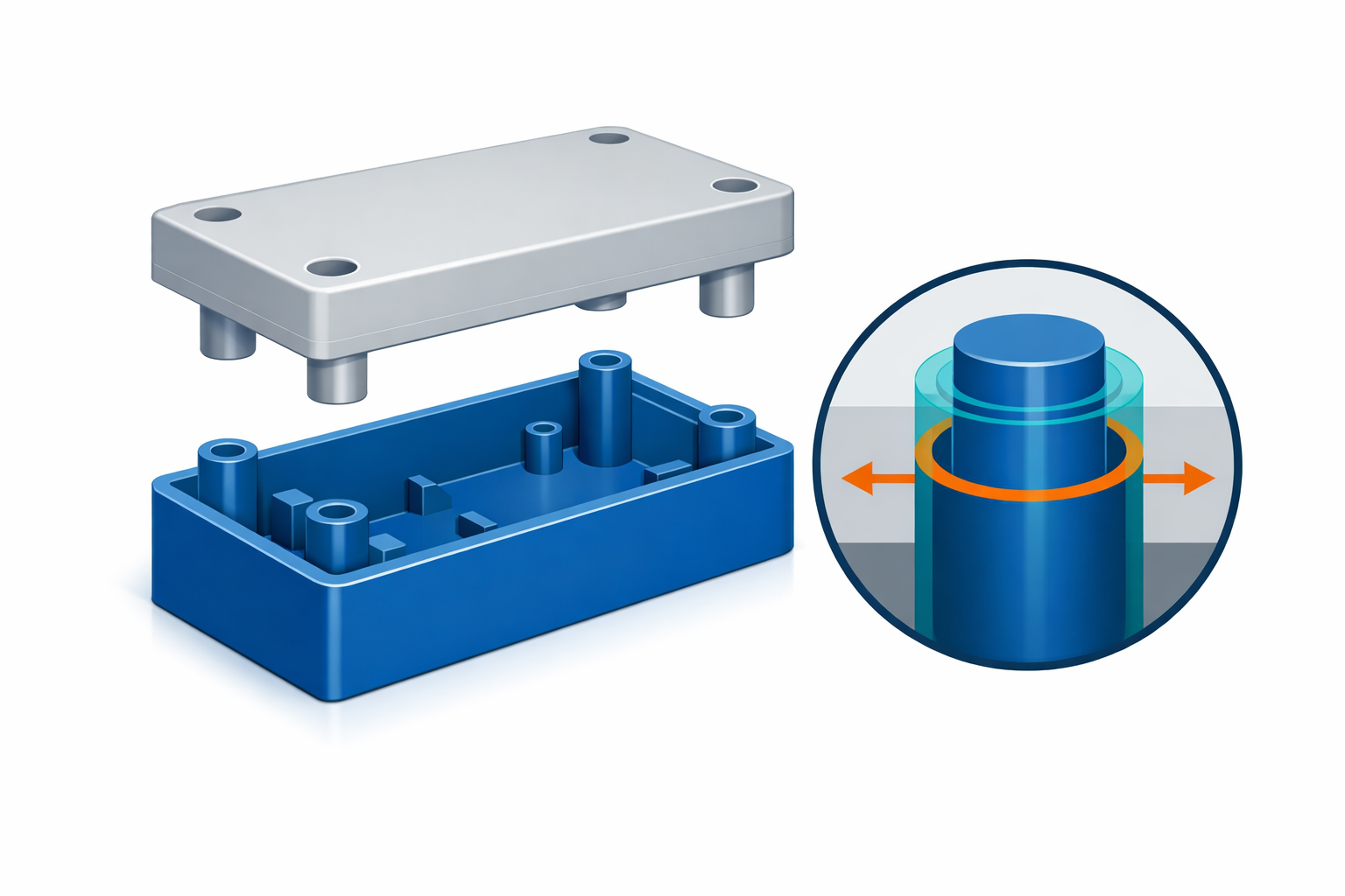
Injection Molding Tolerances: A Practical Guide for Drawings and RFQs
Injection molding tolerances define how much a molded feature may vary from its nominal size, form, orientation, or location. They are not simply numbers to copy into a title block. A useful tolerance connects a functional requirement to a drawing control, a manufacturing plan, and an agreed measurement method.
That distinction matters when a team sends an RFQ. A drawing can look precise while leaving the supplier to guess which interfaces are critical, how a part will be restrained during inspection, or when a moisture-sensitive part should be measured. The result may be avoidable questions, inconsistent quotations, or a tool that is difficult to qualify.
This guide explains how engineers and sourcing teams can specify injection molding tolerances more clearly without assuming that one universal tolerance table fits every plastic part.
What Makes Injection Molding Tolerances Different?
A machined feature is produced by removing material from a stable workpiece. An injection-molded feature is formed while polymer flows into a cavity, packs, cools, shrinks, and is ejected. The final dimension can be influenced by material behavior, part geometry, flow direction, cooling balance, tool construction, process stability, and the conditions under which the part is measured.
This does not mean molded parts cannot be controlled. It means dimensional requirements should be reviewed as a system. A tolerance that is practical for a short feature near a stable datum may be inappropriate for a long dimension that crosses changing wall sections, multiple tool actions, or an assembly stack.
Size is only one kind of requirement
A plus-or-minus dimension controls size, but many product failures relate to geometry rather than size alone. A sealing face may need a form control. A boss pattern may need positional control relative to assembly datums. A wall may need orientation control relative to a mounting surface. The drawing should express the function that actually matters.
For US engineering teams, ASME Y14.5 is an authoritative reference for the language of geometric dimensioning and tolerancing, or GD&T. It establishes rules and symbols for communicating design intent. Applying GD&T correctly still requires engineering judgment about the molded part and its inspection setup.
Start with Function, Not Decimal Places
The most effective first question is not “How tight can this dimension be?” It is “What happens if this feature varies?” That turns tolerancing into a risk-based decision.
For each important feature, record:
- Function: Does it locate, seal, latch, guide, rotate, support, or provide clearance?
- Mating relationship: What other part or fixture interacts with it?
- Failure mode: Could variation cause interference, leakage, rattle, poor alignment, excessive force, or cosmetic mismatch?
- Reference system: Which surfaces or features establish the part in assembly?
- Verification: How will the requirement be measured, and by whom?
This review separates critical-to-function dimensions from general geometry. Noncritical dimensions can then use an appropriate general tolerance, while critical interfaces receive specific controls and a documented inspection plan. A blanket tight tolerance on every dimension can increase tooling and validation complexity without protecting the interfaces that matter most.
Seven Factors That Influence Dimensional Variation
1. Material behavior
Different polymers respond differently during flow, cooling, conditioning, and service. Grade, reinforcement, moisture state, colorant, and supplier-specific data may all matter. A drawing should identify the approved material specification or clearly state where material selection remains open. Generic family names are often insufficient for final tolerance decisions.
2. Part size and measurement span
Variation accumulates across a longer span. A local feature and an overall dimension should not automatically receive the same numerical tolerance merely because they appear on the same drawing.
3. Wall and feature geometry
Wall transitions, ribs, bosses, corners, openings, and thick local sections affect flow and cooling. Uneven behavior can influence dimensions as well as surface appearance. For a deeper discussion of one related defect mechanism, see injection molding sink mark causes and prevention.
4. Flow and gate relationship
The location and direction of feed can influence how a cavity fills, packs, and shrinks. Dimensions measured along the flow path may behave differently from those measured across it, particularly in reinforced materials. Gate strategy should therefore be considered during tolerance review rather than after all drawing requirements are frozen.
5. Tool architecture
Parting lines, inserts, slides, lifters, and multiple cavities introduce interfaces that may affect alignment or repeatability. A dimension that crosses two tool actions deserves different attention from one formed entirely in a stable cavity block.
6. Process window and cooling
Dimensions should remain acceptable across an approved process window, not only on one ideal sample. Packing response, temperature control, cooling balance, ejection, and cycle stability can all affect the final result. Qualification should distinguish a repeatable process from a one-time measurement.
7. Measurement conditions
Inspection results can change with part temperature, elapsed time after molding, moisture conditioning, fixture force, datum simulation, instrument choice, and operator method. If these conditions are not defined, two parties can measure the same feature correctly and still report different results.
Standard Tolerances vs. Tight Tolerances
General or standard tolerances are useful for noncritical dimensions because they keep the drawing readable and establish a common baseline. Tighter tolerances should be reserved for features with a demonstrated functional need.
Before tightening a requirement, ask:
- Is the tolerance driven by an assembly calculation, test result, regulatory requirement, or legacy habit?
- Can the function be protected through clearance, datum strategy, profile control, or a design change instead?
- Does the tolerance apply to every cavity and throughout the expected production life?
- Can the feature be measured repeatably without distorting or over-constraining the part?
- What evidence will qualify the tool and release production?
ISO 20457 addresses tolerances and acceptance conditions for plastics molded parts. Teams should confirm the applicable edition, contractual hierarchy, and drawing conventions for their program. A standards reference is a framework, not a supplier-specific capability guarantee.
Control Tolerance Stack-Up at the Assembly Level
A tolerance stack-up combines the permitted variation of multiple dimensions that influence a final gap, alignment, preload, or clearance. Looking only at individual part dimensions can hide an assembly risk.
Consider a housing, an internal carrier, and a cover. The visible gap at the cover may depend on the housing datum, carrier seat height, cover locating feature, and fastener restraint. Tightening the cover dimension alone may not solve the problem if the largest contributors lie elsewhere.
A practical stack-up review should:
- define the assembly requirement and direction of interest;
- build a dimension chain from functional datums rather than convenient edges;
- include mating parts, fixtures, and any material or environmental condition that changes the interface;
- identify the largest contributors and sensitivities;
- decide whether worst-case, statistical, or test-based analysis fits the product risk;
- assign each critical control to a drawing and verification method.
The goal is not to make every component extremely precise. It is to allocate variation where the assembly can tolerate it and control the few contributors that protect function.
Define Datums, GD&T, and Inspection Conditions
Datums should reflect how the part is located in its real assembly or functional inspection. A convenient flat surface is not automatically the best primary datum. Thin, flexible, textured, or drafted surfaces may also require careful restraint and datum simulation.
For every critical characteristic, the drawing or quality plan should make the following clear:
- the datum reference frame and sequence;
- the controlled feature and applicable material-condition modifier, if any;
- the measurement method and instrument or fixture concept;
- the allowed clamping or restraining force;
- the measurement temperature and conditioning state;
- the time after molding or conditioning at which acceptance applies;
- the sampling or qualification plan and responsibility for acceptance.
Early agreement prevents a common dispute: the drawing contains a requirement, but the buyer and supplier use different setups to decide whether the part meets it.
What to Include in a Tolerance-Ready RFQ
A useful RFQ package gives the molding team enough context to review risk before quoting or committing to tooling. Include:
- a current 3D CAD model and a controlled 2D drawing;
- revision identifiers and a clear hierarchy if files conflict;
- critical-to-function dimensions and the reason each matters;
- assembly datums, mating-part information, and relevant stack-up calculations;
- the material specification or the functional requirements that will guide selection;
- cosmetic surfaces and acceptance references where applicable;
- expected service conditions that could affect dimensions;
- measurement, conditioning, sampling, and reporting expectations;
- forecast volumes as planning inputs, without treating them as a dimensional requirement;
- open questions that must be resolved during design-for-manufacturability review.
A 3D model alone may communicate nominal geometry but not acceptance criteria. A 2D drawing alone may omit the functional context behind its tolerances. Supplying both, with controlled revisions, gives the review team a stronger starting point.
Common Tolerancing Mistakes
- Copying machined-metal tolerances onto molded plastic: the material and forming process behave differently.
- Using the same decimal precision everywhere: displayed digits are not a substitute for functional analysis.
- Over-controlling cosmetic or nonmating features: this consumes attention without reducing meaningful risk.
- Dimensioning from unstable edges: functional datums usually provide a clearer assembly reference.
- Ignoring measurement state: temperature, moisture, elapsed time, and restraint can alter the result.
- Freezing tolerances before gate and tool review: tool architecture and flow strategy can change what is practical.
- Qualifying one sample instead of a process: repeatability across cavities and an approved process window matters.
Pre-Tooling Tolerance Review Checklist
Before authorizing tooling, confirm that the team can answer these questions:
- Which dimensions are truly critical to fit, form, or function?
- What assembly calculation or test supports each tight requirement?
- Do the datum scheme and inspection setup represent actual use?
- Have material, flow, cooling, geometry, and tool-action effects been reviewed?
- Are measurement conditions and acceptance responsibilities documented?
- Has the tolerance stack-up been checked across all mating components?
- Are unresolved risks assigned to an owner and a validation step?
This checklist does not establish an achievable tolerance for a specific part. It creates the evidence needed for an informed design and tooling discussion.
Frequently Asked Questions
Is there one standard tolerance for all injection-molded parts?
No. Standards and general tables can provide a framework, but the appropriate requirement depends on material, feature size, geometry, tool design, process plan, function, and measurement conditions. A specific commitment requires part-level review.
Should every dimension on a molded-part drawing have a tight tolerance?
No. Tight controls should protect critical functions. Noncritical dimensions can usually follow an appropriate general tolerance so that engineering, tooling, and inspection effort stays focused on real product risk.
Is a 3D CAD model enough for an injection molding RFQ?
It may be enough for an early feasibility conversation, but it rarely defines all acceptance requirements. A controlled 2D drawing is useful for critical dimensions, datums, GD&T, notes, revisions, and measurement conditions.
When should tolerance stack-up be reviewed?
Review it while the assembly and part geometry can still change, then revisit it after material, tool architecture, and measurement plans are better defined. Waiting until tool qualification limits the available corrective options.
Does a prototype prove production molding tolerances?
Not by itself. A prototype can provide useful fit or interaction evidence, but it may not reproduce production material behavior, mold cooling, cavity relationships, process variation, or the final inspection method.
What should a buyer ask a molding supplier before tooling?
Ask how critical dimensions will be reviewed, what assumptions affect the quotation, how datums and measurement conditions will be interpreted, what evidence will qualify the tool, and which open risks require a design decision.
Prepare the Engineering Conversation
Clear injection molding tolerances begin with function, not a generic capability claim. If you are preparing a molded-part RFQ, review the available manufacturing service information, then share your controlled drawing and functional requirements for a project-specific discussion. Final dimensional commitments should always be confirmed against the actual part, material, tooling plan, process, and inspection agreement.