Injection Molding Sink Marks: Causes and Prevention


A sink mark is a shallow depression on the surface of an injection molded part. It often appears opposite a rib, boss, internal fillet, or other locally thick section. The visible defect is on one side of the part, while the feature that caused it may be hidden on the other.
The fastest route to a correction is not to increase holding pressure at random. First determine whether the limiting cause is part geometry, the feed path, packing, cooling, material behavior, or a combination of these factors. That distinction tells the team whether the next move belongs in the CAD model, the mold, or the process window.
What Is a Sink Mark in Injection Molding?
During molding, the material next to the cooler mold surface solidifies before the material in the center of a thick section. As the core continues to cool, it contracts. If enough additional material cannot reach that area during packing, the contraction can pull the surface inward and leave a visible depression.
Autodesk describes sink marks and internal voids as two possible outcomes of localized shrinkage without sufficient compensation. A flexible outer skin may move inward and form a sink mark. If the skin is rigid enough to resist that movement, a void may form inside instead. This is why a clean-looking surface does not automatically prove that a heavy section is free of internal risk.
Where Sink Marks Usually Appear
Start the investigation by comparing the defect location with the geometry on the opposite face. Common risk areas include:
- the back of a rib-to-wall intersection;
- the surface opposite a screw boss;
- a heavy internal fillet or mounting pad;
- an abrupt wall-thickness transition;
- a solid section that could have been cored out;
- a thick area located far from a gate or behind a thinner section that freezes earlier.
Cosmetic finish also changes how visible a sink mark appears. Reflections can make a small depression conspicuous on a smooth or glossy surface. A textured surface may hide a minor depression, but texture does not remove the underlying shrinkage. The cosmetic requirement should therefore be defined before the tool and finish are approved.
The Five Main Cause Groups

1. Localized thick geometry
A rib, boss, fillet, or solid mounting feature can create a local mass that cools more slowly than the surrounding wall. The outer surface freezes first, while the warmer core continues to shrink. If the defect repeatedly appears in the same location and maps directly to a heavy feature, geometry should be investigated before the team relies on process changes.
Published design guidance often treats ribs and bosses as features that should remain thinner than the wall they support. Protolabs, for example, gives a 40–60% wall-thickness range for boss walls and advises that ribs and gussets should not exceed 60% of nominal wall thickness. These are orientation rules rather than universal acceptance criteria. Resin, wall thickness, flow, strength requirements, mold construction, and surface expectations can change the appropriate value for a specific part.
2. Insufficient packing or early gate freeze
After the cavity fills, packing pressure supplies additional material to compensate for shrinkage. If pressure is too low, the effective packing time is too short, or the gate freezes before the heavy area is adequately packed, the cavity can no longer receive enough material where it is needed.
A process change may help when the geometry is moldable but the packing profile is not robust. However, increasing pressure without a diagnosis can create other problems, including flash, residual stress, or overpacking closer to the gate. The correction must be judged across the entire part, not only at the visible dimple.
3. Gate and runner limitations
Gate location and feed-path restriction affect whether packing pressure reaches a sink-prone region before intervening sections freeze. A thick feature located beyond a long or restrictive path may be difficult to compensate even when machine pressure is available.
Questions for the tooling and molding teams include:
- Does the defect sit far from the gate?
- Does a thinner section between the gate and defect freeze first?
- Does the sink respond to longer holding time, or has the gate already sealed?
- Would changing the gate location or size improve packing but create a new vestige, weld-line, flow, or cosmetic issue?
A gate change is a tooling decision with multiple consequences. It should not be presented as a one-variable cure.
4. Cooling and temperature imbalance
Cooling conditions influence how quickly the skin and core solidify. A local hot spot, uneven cooling around a heavy feature, or a temperature setting that increases shrinkage risk can make a depression more visible. Extending cooling may change the point at which the part is ejected, but cooling time alone does not remove the extra material mass created by poor geometry.
When a sink mark varies between cavities, cycles, or production runs, compare mold-temperature control, coolant flow, actual cycle conditions, and cavity-specific behavior. Repeatability is useful evidence: a fixed, geometry-aligned defect suggests a different path from an intermittent defect that tracks process drift.
5. Material shrinkage behavior
Different resin grades have different shrinkage, viscosity, reinforcement, moisture, and processing requirements. A material change can alter sink risk, but it can also change warpage, surface appearance, strength, dimensions, regulatory obligations, or assembly performance.
Do not change material solely to hide a cosmetic symptom. Review the approved material specification and the functional requirements first, then evaluate any alternative with the designer, molder, and relevant quality stakeholders.
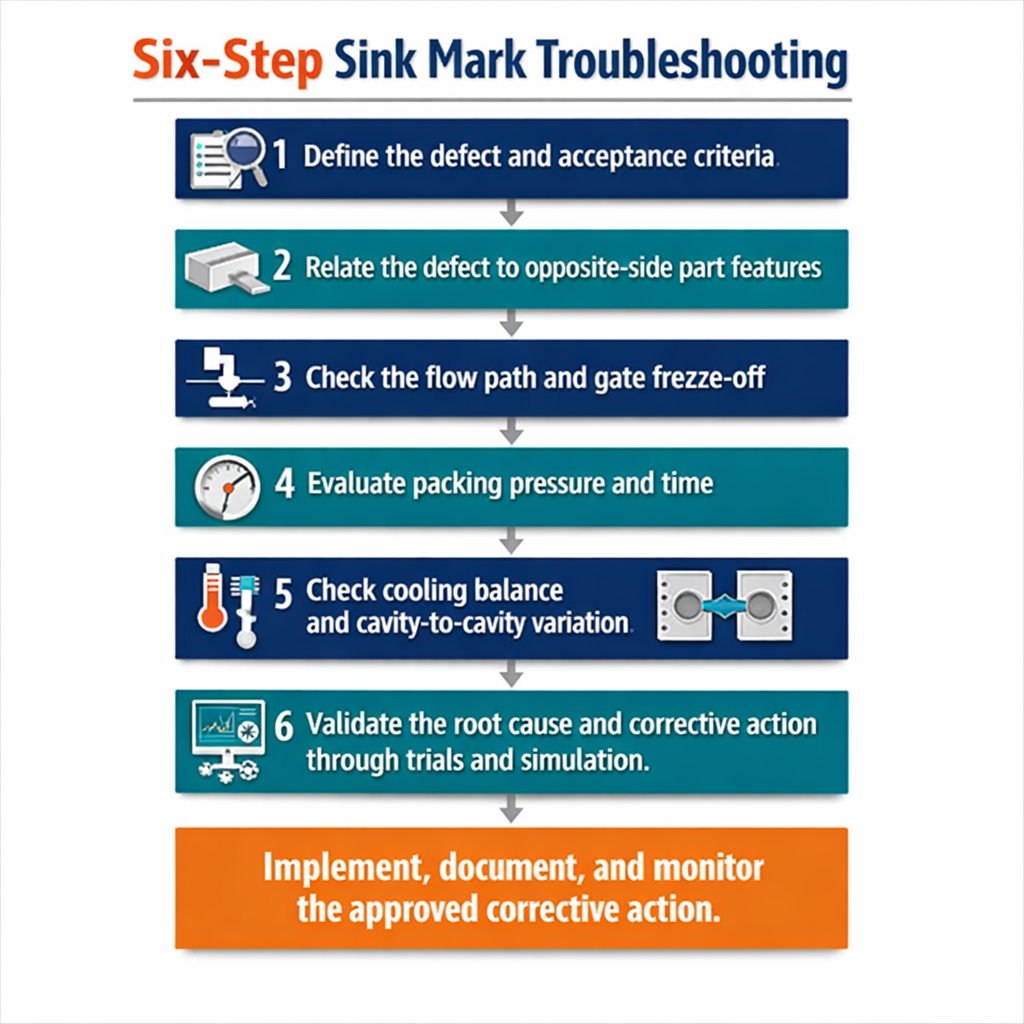
A Practical Troubleshooting Sequence
Step 1: Define the defect and acceptance requirement
Record the exact location, side, cavity, sample stage, lighting condition, surface finish, and part revision. Mark whether the area is cosmetic, dimensional, structural, or hidden after assembly. A photo without the part revision and viewing conditions is weak evidence.
Step 2: Map the sink to the opposite-side geometry
Overlay the defect location on the CAD model. Check ribs, bosses, fillets, wall transitions, and concentrated material. Measure the relevant section rather than judging it by appearance. If the sink aligns with a heavy feature, explore coring, thinning, relocating, or reinforcing that feature without adding another local mass.
Step 3: Check the feed path and gate-seal behavior
Review the gate location, gate section, runner path, and the thickness between the gate and the defect. A structured hold-time study can help determine when part weight stops increasing, which is useful evidence about gate seal. The exact study method and acceptance criteria should be defined by the molding team for the tool and material.
Step 4: Review the packing response
Change one controlled variable at a time and document the response. If a reasonable packing adjustment materially reduces the sink without introducing flash, stress, or another defect, the process window may have room for improvement. If the mark barely changes, revisit geometry, feed restrictions, and cooling rather than escalating pressure indefinitely.
Step 5: Compare cooling and cavity behavior
Check whether the defect changes with mold temperature, cooling stability, cycle conditions, or cavity. A cavity-specific pattern can point toward local tooling or cooling differences. A part-wide pattern may indicate a broader process or material effect.
Step 6: Use simulation as evidence, not as a guarantee
Fill-and-pack analysis can help identify predicted sink locations, volumetric shrinkage, pressure delivery, and gate effects before steel changes are made. Simulation quality depends on the mesh, material data, process assumptions, and model setup. Confirm predictions against trial data and do not treat a simulation image as proof that production parts will be defect-free.
Design Actions That Reduce Sink Risk
- Keep wall thickness as uniform as the function allows. Replace abrupt heavy sections with gradual transitions where practical.
- Core out solid bosses and pads. Use ribs or gussets to support them rather than filling the surrounding area with material.
- Keep ribs and gussets appropriately thinner than the adjoining wall. Treat published ratios as a starting point to validate against the selected resin and structural requirement.
- Avoid oversized internal fillets. A fillet can reduce stress concentration, but an excessively heavy intersection can increase sink risk.
- Identify cosmetic surfaces early. Gate vestige, parting lines, ejector marks, weld lines, and sink acceptance should be reviewed together.
- Review strength and assembly after any thinning. Removing mass can reduce sink while weakening a fastening or load-bearing feature if the change is not checked.
For broader manufacturability planning, see FULU Plastics’ mold design and manufacturing overview. The current page is a commercial overview; this article remains a neutral troubleshooting guide.
What to Include in a Sink-Mark Corrective-Action Record
A useful record should allow a buyer, designer, toolmaker, and molder to see why a change was selected. Include:
- part number and CAD/drawing revision;
- resin grade and color, without substituting an unapproved alternative;
- tool, cavity, machine, and sample stage;
- annotated photos under defined viewing conditions;
- defect location mapped to CAD geometry;
- baseline process and controlled trial changes;
- gate-seal or part-weight evidence where relevant;
- the proposed CAD, tooling, cooling, or process action;
- side effects checked, such as flash, warpage, dimensions, stress, strength, and cycle stability;
- owner, approval status, revision, and verification result.
This prevents the project from becoming a sequence of undocumented parameter changes and makes it easier to distinguish a temporary cosmetic improvement from a stable correction.
Questions Buyers Should Ask Before Approving a Fix
- Is the sink primarily geometry-driven, feed-path-driven, process-driven, or still unconfirmed?
- What evidence connects the proposed action to the root cause?
- Has the response been checked across cavities and repeated cycles?
- What new risks could the change introduce?
- Does the correction require a CAD revision, steel change, process-window update, or material approval?
- How will the revised sample be inspected and accepted?
If you are preparing a molded-part review, FULU Plastics provides an overview of its injection molding service and general services. For a project-specific discussion, send the current CAD model, drawing revision, approved resin requirement, cosmetic-surface definition, expected quantity, and photos or sample data through the contact page. Any recommended action should be confirmed against the actual part, tool, and process before implementation.
Frequently Asked Questions
Can higher packing pressure always remove sink marks?
No. More packing can help when insufficient compensation is the limiting cause and the gate remains open long enough to transmit pressure. It has limited value when thick geometry, an early-frozen feed path, or uneven cooling is the dominant cause. Excessive pressure can also create new defects.
What is the difference between a sink mark and a void?
A sink mark is a surface depression. A void is an enclosed internal cavity. Both can result from localized shrinkage in a thick section. Which one forms depends partly on whether the outer skin deforms or remains rigid as the core contracts.
Are sink marks only cosmetic?
Often they are treated as a cosmetic defect, but the surrounding geometry may also affect dimensions, assembly, or strength. Internal voids can have structural consequences. Acceptance should be based on the part’s function and drawing requirements, not appearance alone.
Should a designer always use the same rib-to-wall ratio?
No. Published ratios are useful starting points, not universal rules. The appropriate geometry depends on resin, nominal wall, flow, tool design, strength requirements, surface finish, and the molding process. Confirm the design with the supplier and validate it against the specific project.
When should sink risk be reviewed?
Review it during part DFM, before tooling approval, again during mold-design review, and at sampling. A late review reduces the available correction options and may turn a CAD change into a tool modification.